 |
|||
| Updated on August 27, 2012 | |||
| 科学研究費補助金 挑戦的萌芽研究プロジェクト (平成23〜25年度) 「チタニアナノチューブ/ナノ酸化鉄ピーポッド配向薄膜の創製と光磁気デバイスへの展開」 |
|||
| (準備中) | |||
| 酸化物系1次元ナノ材料合成PJ (One-Dimensional Nanomaterials Projects) | |||
| (1) 水熱・熱処理複合プロセスによる酸化チタン誘導ナノチューブの合成と構造制御 | (1) Synthesis and Thermal Analysis of TiO2-Derived Nanotubes Prepared by Hydrothermal Method | ||
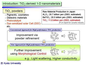 |
TiO2 powders are widely used for industrial applications, such as pigments,
cosmetics, catalysts, catalyst supports, electronic devises and so on.
Fine TiO2 powders have received considerable attention for their high photocatalytic activity, and are applied for environmental purification, and antibacterial purposes. Recently, they are also applied for dye-sensitized solar cells. To improve the various functions, morphological control has been conducted as well as the convensional powder refinement. |
||
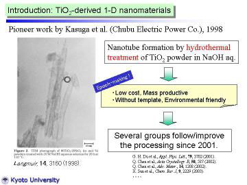 |
TiO2-derived nanotubes obtained by the hydrothermal alkali treatment method have been attracted much attention since the innovative work by Kasuga et al. in 1998-99, because of their fascinating microstructure and promising photo electrochemical applications. The nanotubes can be prepared by simple (cost-effective) and environmentally innoxious processing. Several groups have tried to improve or to modify the yield and structure of the nanotubes. |
||
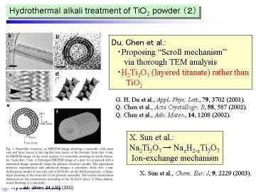 |
Some recent studies suggest the as-prepared nanotubes by the hydrothermal
method contained a fair amount of water, and stated that they should be
recognized as trititanate H2Ti3O7. We consider that such hydrated structure will offer another possibility to design various TiO2-relating structures by post-treatments, such as well-controlled heat or low-temperature plasma treatment. |
||
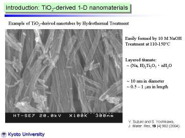 |
TiO2-derived nanotubes were prepared by hydrothermal treatment of TiO2
powder in NaOH aqueous solution. The nanotube preparation method was basically the same as described in previous papers. A commercial, fine TiO2 (anatase) powder (Ishihara Sangyo Ltd., ST-01) was used as a starting material. In typical manner, 150 mg of TiO2 powder was dispersed in NaOH aqueous solution (10 M, 50 ml), and put into a Teflon-lined stainless autoclave. The autoclave was heated at 110 deg C for 72 h. After it was cooled to room temperature, the precipitated powder was washed with HCl aqueous solution and distilled water, and dried in a rather mild condition (60 deg C for 12 h). |
||
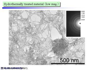 |
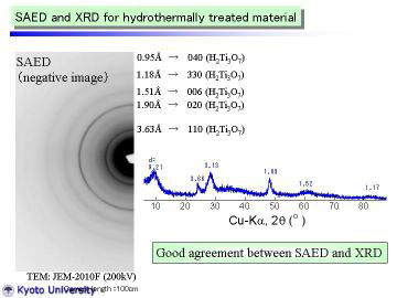
Left figure shows a TEM micrograph (low magnification) of TiO2-derived nanotubes; the insert indicates a selected area electron diffraction (SAED) pattern for group of nanotubes. A large quantity of rather long nanotubes (~ 1 micrometer in length) can be seen in the picture. There were some particle-like portions in the figure, | ||
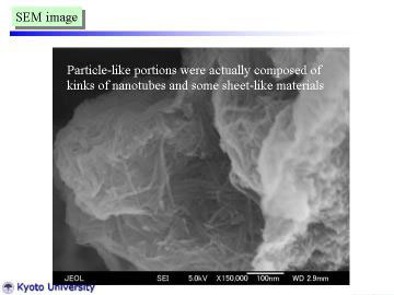 |
But the particle-like portions were actually composed of kinks of nanotubes. Some sheet-like structure was also found in the obtained nanotubes. The nanotubes had a diameter of ~ 10 nm, which was in good agreement with previous studies. | ||
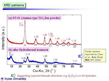 |
XRD patterns obtained at room temperature are given: (a) starting material and (b) nanotubes synthesized by the hydrothermal method. The starting powder consisted of pure and fine anatase phase. In contrast, the as-synthesized nanotube powder had a different crystal structure. It can be assigned to trititanate H2Ti3O7 as proposed by Peng's group, but more preferably expressed as H2Ti3O7.nH2O, we think. The reflection peak at d~9.2A (0.92nm) corresponds to the 200 reflection, which should be expanded by interlayer H2O molecules. Note that the 200 reflection of H2Ti3O7 phase prepared by conventional solid-state reaction and ion-exchange method was at d=7.87 A, reported by Feist et al. | ||
 |
|||
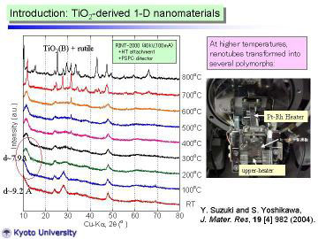 |
Left figure shows HT-XRD patterns for the as-synthesized nanotubes. XRD pattern at 100oC was almost the same as that at RT., however, the peak near 2 theta=10o slightly shifted toward higher angle (in other words, became narrower d-spacing). At 200oC, clear peak shift (to 2theta = 11.2°) was observed. The reflection peak at 11.2° corresponds to the 200 reflection of H2Ti3O7 phase, d200 ~ 7.9 A. viz., the interlayer spacing of layered titanate. The peak-shift behavior from room temperature to 200oC can be well-explained by the dehydration of interlayer water. XRD pattern changed drastically at 700oC, and further change was observed at 800oC. At 800oC, TiO2(B) phase (a metastable polymorph of titanium dioxide ) and rutile phase were identified. | ||
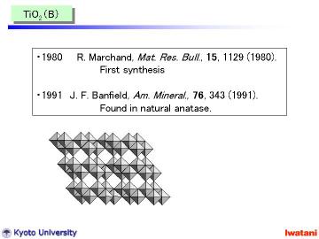 |
TiO2 (B) was firstly reported by Marchand and Tournoux et al. in 1980.
And later, in 1991, naturally occurring TiO2 (B) was also identified in
a natural anatase crystal by Banfield et al. Feist et al. studied the formation
mechanism of TiO2 (B) from various layered titanates in detail. According to the Feist's report, observed phases at 700oC (and some unindexed peaks at 800oC) can be attributable to intermediate phases, such as HTi3O6.5 and H0.5Ti3O6.25. |
||
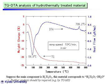 |
TG-DTA curves of the as-prepared TiO2-derived nanotubes are given. The
endothermic peak at 84.4 deg C is attributable to the desorption of adsorbed
water. At ~ 120 deg C, TG curve was slightly inflected (i.e., became gentle),
which may correspond to the dehydration of interlayer water. Above 200
deg C, weight loss became much gentler, suggesting the slow evaporation
of structural water in H2Ti3O7. These phenomena are in very good agreement with those of HT-XRD study. The exothermic peak at 709 deg C is presumably attributable to the latent heat for the phase transformation from metastable TiO2(B) to stable rutile phase. From TG curve, the composition of as-prepared nanotubes (mildly dried and handled in normal air atmosphere) can be expressed as H2Ti3O7.3H2O. |
||
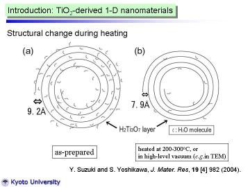 |
The present HT-XRD work demonstrated that the reflection at d~9.2A can be well-explained by the swelling via water intercalation into 200 plane of H2Ti3O7. In addition, TiO2 (B) (dehydration product of H2Ti3O7) was actually identified during the heating process. | ||
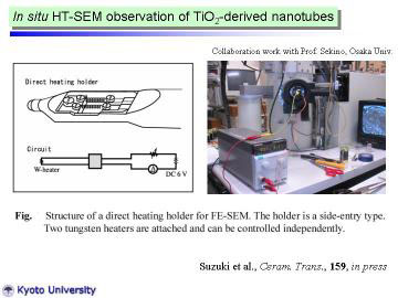 |
To clarify the microstructural change during the heat-treatment, preliminarily
in situ high- temperature SEM observation has been carried out. In situ HT-SEM observation was preliminarily conducted using a field emission scanning electron microscope (SEM, Hitachi, S-5000) attached with tungsten-coil heating stage. |
||
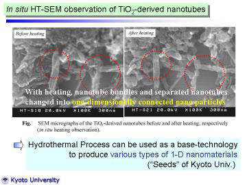 |
Left figures show SEM micrographs of the TiO2-derived nanotubes before and after heating, respectively. Before heating, nanotube bundles and separated nanotubes were observed. With heating, nanotube bundles and separated nanotubes changed into one-dimensionally connected nano particles. This direct observation well explains the fact that the nanotube structure of the hydrothermally prepared TiO2-derived nanotubes became unstable around 500oC, and changed into anatase-type particles or dense fibers. This HT-SEM study suggests a future possibility that the hydrothermally prepared TiO2-derived nanotubes can be used as precursor for one-dimensional nanostructured TiO2. | ||
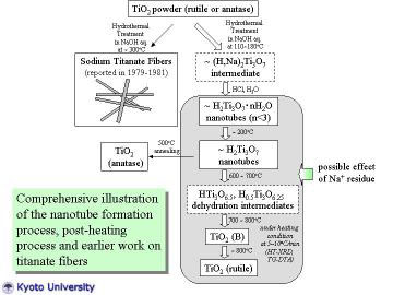 |
The nanotube formation process, post-heat treatment process, and earlier work on titanate fiber processing by Watanebe et al. are comprehensively illustrated. In this study, TiO2-derived nanotubes were prepared by hydrothermal treatment of TiO2 powder in NaOH aqueous solution. HT-XRD and TG-DTA studies revealed the dehydration and the phase transformation behavior of nanotubes. The constituent phase of the as-prepared nanotube can be assigned most probably as H2Ti3O7.nH2O (n < 3). Post-treatment for nanotubes enabled to produce TiO2-related metastable materials (e.g. TiO2 (B)), and such metastable materials are also promising for photo electrochemical and catalytic applications like titanate nanotubes. | ||
 |
|||
| For more details... |
Y. Suzuki, and S. Yoshikawa, "Synthesis and Thermal Analyses of TiO2-Derived Nanotubes Prepared by the Hydrothermal Method,"J. Mater. Res., 19 [4] 982-985 (2004). Y. Suzuki, S. Sakulkhaemaruethai, R. Yoshida and S. Yoshikawa, "Heat Treatment Effect on the Structure of TiO2-Derived Nanotubes Prepared by Hydrothermal Method," (Proc. 106th ACerS Annual Meeting, 2004) Ceram. Trans., 159, 185-192 (2005). R. Yoshida. Y. Suzuki and S. Yoshikawa, "Effects of Synthetic Conditions and Heat Treatment on the Structure of Partially Ion-Exchanged Titanate Nanotubes," Mater. Chem. Phys., 91 [2-3] 409-416 (2005). |
||
|
|
|||
| (2) 酸化チタンナノワイヤーの色素増感太陽電池への応用 (Apprication of TiO2 nanowires for dye-sensitized solar cells) | |||
| (近日公開予定) |
Coming soon. | ||
|
|
|||
| (3) 低環境負荷プロセスを用いた天然ルチルの高機能化 - 層状チタン酸およびTiO2ナノファイバーの合成と応用 - (岩谷産業との共同研究)(Low cost and Environmentally Friendly Processing of Layered Titanate and TiO2 nanofibers from Natural Rutile, collaborative work with Iwantani International Co.) | |||
 |
Currently, high-purity TiO2 fine powders are industrially produced by the sulfate process from ilmenite (mineral FeTiO3) and the chloride process from natural or synthetic rutile (~95 % TiO2). These industrial processes have their own excellent features, however, some weak points actually exist: iron sulfate waste problem for the sulfate process, and high installation/operating costs for the chloride process. Further cost reduction and environmental compatibility are indispensable for spreading TiO2 nanomaterials |
||
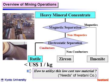 |
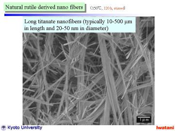
In this study, we report the synthesis of layered titanate nanofibers using
natural rutile as a starting material. It might be worthy of note that the cost of natural rutile sand used in this study is < US$ 1/kg, which is 1/50-1/100 of a commercial rutile or an anatase powder in an ordinary grade. By using natural rutile granules for the hydrothermal NaOH (aq.) treatment, rather long (10-500 micrometer) sodium hydrogen trititanate ((Na,H)2Ti3O7) nanofibers with diameters of typically 20-50 nm have been successfully obtained. Microstructure and possible formation mechanism of the nanofibers will be discussed. |
||
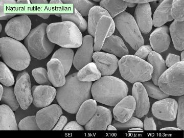 |
Natural rutile sand (brown-colored, yielded in Australia, 96.0% TiO2, Tiwest Sales Pty. Ltd.) was used as a starting material. The granules, with the size of 75-300 micrometer, had rather rounded shape, however, some facet-like planes were also observed. | ||
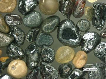 |
Left figure shows an optical micrograph of the natural rutile sand. Some whitish inclusions are thought to be ZrSiO4, or aluminosilicate based minerals. | ||
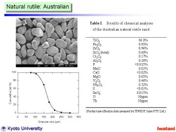 |
Table I summarizes the chemical composition of the Australian natural rutile sand. | ||
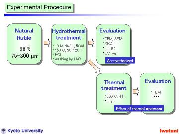 |
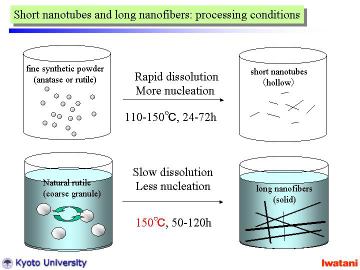
The hydrothermal method was basically similar to that in the previous reports for nanotubes and nanowires preparation, except for the starting material and the slightly higher (at 150oC) and longer (for 50 or 120 h) hydrothermal conditions. In a typical manner, 300 mg of the natural rutile granules (75-300 micrometer) was added into NaOH aqueous solution (10 M, 50 ml), and put into a Teflon-lined stainless autoclave. The autoclave was heated at 150 oC for 50 h in static condition, or at 150oC for 120 h with magnetic stirring. It was cooled to room temperatur |
||
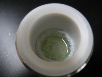 |
Although the starting natural rutile was brown-colored, the obtained nanofibers became almost white (very slightly yellowish). This phenomenon indicates that a large portion of Fe impurities can be removed by the NaOH (aq) hydrothermal treatment and following neutralization/washing processes. | ||
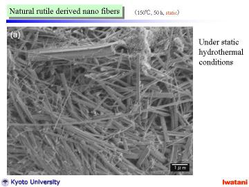 |
The obtained nanofibers had high linearity and were rather long, 10-500
micrometer, compared with reported nanotubes Under static condition and relatively shorter treatment time, some particle-like portion (upper-right in the figure), or unreacted rutile granule (~several micron in size) coexisted in the product. |
||
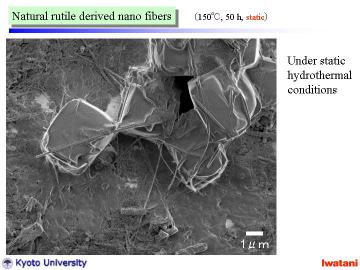 |
Unreacted rutile granule (~several micron in size) | ||
 |
However, for longer reaction time and with magnetic stirring, unreacted
material disappeared in the product and better nanofibers were obtained. Each single fiber had a typical diameter of 20〜50nm, and formed some bundles of several hundred nm in diameter. |
||
 |
|||
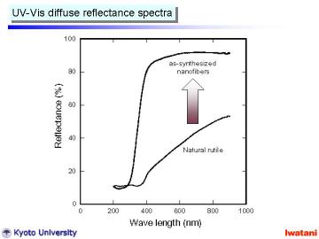 |
Left figure shows UV-Vis diffuse reflectance spectra of (a) natural rutile
and (b) as-synthesized nanofibers. This figure clearly demonstrates the
removal of the visible-light absorbing ions via NaOH (aq) treatment. In addition, the absorption edge shifted to lower wavelength. Such blue shift has been also reported for hydrothermally prepared TiO2-derived nanotubes. It can be explained by the size effect, crystal structure change into titanate (as described later) and chemical state change (i.e. existence of Na+ ions and -OH surface group). |
||
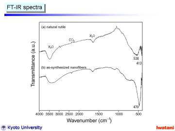 |
Left figure shows FT-IR spectra of (a) natural rutile and (b) as-synthesized
nanofibers. Natural rutile had absorption bands at 538 cm-1 and 413 cm-1,
which are characteristic ones for rutile phase. In contrast, the as-synthesized nanofiber had rather sharp absorption band at 470 cm-1, indicating the formation of trititanate structure. Furthermore, the broadening of ~3400 cm-1 O-H stretching vibration the formation of a different -OH group, and most probably as Ti-OH surface group. |
||
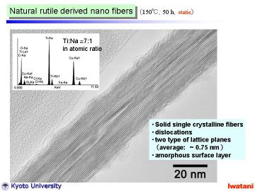 |
Left figure shows a TEM photograph of an as-synthesized nanofiber, hydrothermally
synthesized at 150oC for 50 h under static condition. The fiber was solid (not hollow) with d-spacing of ~ 0.75 nm and was different from nanotubes reported. Some dislocation-like structure can be seen within the nanofiber, and amorphous-like layer on the surface. Typical EDS spectrum of a nanofiber is inserted, which indicates the existence of residual Na ion (Ti:Na = 7:1 in atomic ratio). The Na content in the nanofibers can be reduced by repeated HCl leaching and H2O washing. However, when compared with the titanate nanotubes, the nanofibers tended to contain more residual Na ions under the same ion-exchanging conditions. The primary reason of this difference is attributable to the geometry of nanofibers, i.e. solid and thicker structure. It is deduced that the possible crystal structure of the nanofibers will be proton-exchanged hexatitanate, (Na,H)2Ti6O13, or trititanate, (Na,H)2Ti3O7. It is known that alkali-metal hexatitanates (A2Ti6O13, A= Na, K, Rb) tend to form solid fibrous structure, which contain one-directional tunnels along with b-axis. Alkali metal ions in these tunnels usually are stable, and do not leach out so easily via aqueous HCl treatment at room temperature. In this study, although some Na ions still remained within the fiber, large portion of them were leached out. Combining the electron diffraction and X-ray diffraction, the nanofibers obtained in this study should be mainly composed of proton-exchanged layered trititanate, (Na,H)2Ti3O7, with open channel structure. |
||
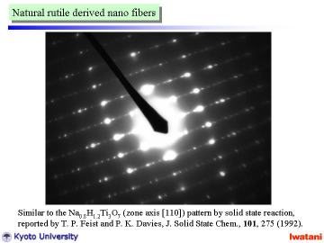 |
Left figure shows an electron diffraction pattern obtained from a single nanofiber. Although there existed some disordering (due to the curvature and defects of nanofibers), the observed pattern indicated that the nanofiber was composed of a single crystal. This electron diffraction pattern closely resembles that of Na0.8H1.2Ti3O7 (zone axis [110]) prepared by the solid state reaction and acid exchange technique reported by Feist and Davies. |
||
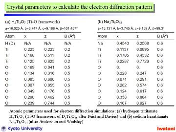 |
To analyze the obtained electron diffraction pattern, those of H2Ti3O7 (Ti-O framework) and Na2Ti6O13 are calculated from the reported atomic parameters given in left Table by using MacTempas software. Note that the curvature of nanofibers was not taken into account for the simulation. | ||
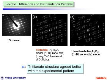 |
As can be seen from above Table, the unit cell dimensions of both structures
are fairly similar to each other, and thus, the diffraction patterns become
also similar to one another. However, the spot intensities for these two structures are rather different. The trititanate structure (b) seems to agree better with the experimental pattern. Some disorder and overlapped spots might be explained by the partial topotactic condensation model described before. According to FT-IR, TEM, EDS and electron diffraction results, it can be concluded that the nanofibers obtained in this study had an approximate composition of Na0.4H1.6Ti3O7. |
||
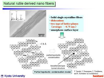 |
The above-mentioned dislocation-like turbostratic structure is then attributable
to the topotactic condensation at some part of the (Na,H)2Ti3O7 nanofiber: 2(Na,H)2Ti3O7 -> (Na,H)2Ti6O13 + H2O (or Na2O) This partial topotactic condensation model (in other words, (Na,H)2Ti6O13-type defect in (Na,H)2Ti3O7 nanofibers) well explains the slightly shorter interlayer spacing of d200~0.75 nm (cf. d200~0.79 nm for an ordinary trititanate), and explains the residual Na ions trapped within nanofibers. The formation of rather defective structure might be attributable to some residual impurities, e.g., SiO2, |
||
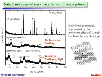 |
Left figure represents XRD patterns of (a) starting natural rutile granules,
(b) as-synthesized titanate nanofibers (synthesized at 150oC for 120 h with magnetic stirring), and (c) titanate nanotubes prepared
from a commercial fine anatase powder as a reference. In (a), all peaks except 2theta=25.3o can be assigned to the reflections of TiO2-rutile phase. The peak at 25.3o is attributable to the strongest reflection 101 of TiO2-anatase phase, which indicates that the natural rutile sand contained a small amount of anatase. The natural rutile had high crystallinity as can be seen from the sharp peaks. As shown in (b), the peak at 11.5-12o (d~0.77-0.73 nm) corresponds to the 200 reflection of layered trititanate, (Na,H)2Ti3O7. In the case of nanotubes (c), the 200 reflection of trititanate was shifted to a lower diffraction angle (i.e., larger d-spacing) due to the swelling by interlayer H2O molecules. In contrast, such a swelling was not observed for the nanofibers (b). This result well agreed with the TEM observation that the titanate nanofibers in this study had solid (not hollow) structure with d-spacing of ~0.75 nm, and coincided with the partial topotactic condensation model where the swelling should be suppressed by the anchoring effect of tunnel structure. |
||
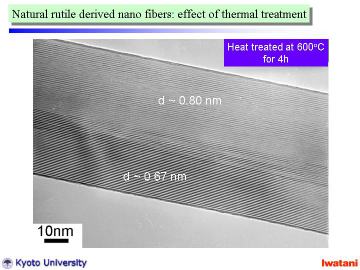 |
The as-prepared nanofibers in this study contained some surface amorphous-like layer and internal dislocation-like defects. Amorphous layer can be cured by a post heat-treatment at 200-300oC, and the number of dislocation-like defect can be decreased by a heat-treatment at 500-600oC. Left figure demonstrates a TEM photograph of a titanate nanofiber after heat-treatment at 600oC for 4h in air. The surface amorphous layer disappeared and the topotactic condensation from trititanate (Na,H)2Ti3O7 (d~ 0.80 nm) to hexatitanate (Na,H)2Ti6O13 (d~0.67 nm) progressed. The nanofibers apparently keep their long-fibrous morphology at ~800oC. | ||
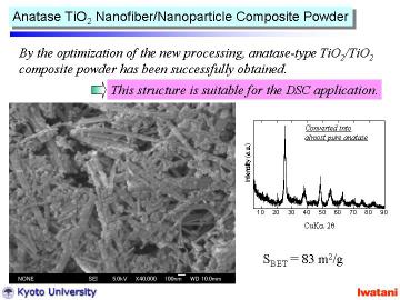 |
By changing the HCl ion-exchanging condition, anatase TiO2 nanofiber/nanoparticle composite powder with higher surface area can be obtained. | ||
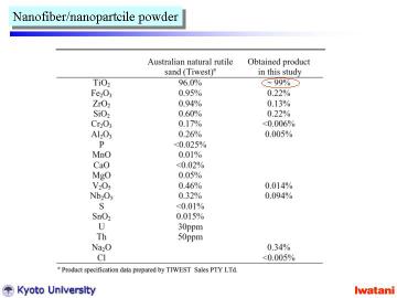 |
Left table summarizes the chemical composition of the starting natural rutile and that of the final product in this study. A large part of impurities in natural rutile can be successfully eliminated by the direct hydrothermal process. |
||
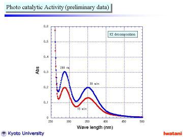 |
Left figure shows preliminary data of the photocatalytic activity measurement
using I3- formation (see UV-Vis peak at 288 and 352 nm) from KI solution using UV
radiation (l = 365 nm). The nanofiber/nanoparticle composite powder actually possessed photocatalytic activity, which seemed to be comparable to that of a commercially available TiO2 nanopowder. |
||
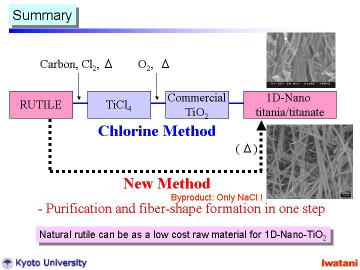 |
Although the further evaluation and optimization should be conducted in detail, the preliminary result is encouraging toward practical applications of the new direct process and the new composite powder. This new process is potentially cost-effective, and can be an alternative industrial process for the TiO2 production with environmental compatibility. It should be noted that the main by-product of this series of processing was NaCl, and the maximum operating temperature was only 150oC, which means an environmentally-friendly process. | ||
| For more details... (including TiO2 (B) and TiO2 anatase fiber processing) | Y. Suzuki, S. Pavasupree, S. Yoshikawa, and R. Kawahata, "Natural Rutile-Derived
Titanate Nanofibers Prepared by Direct Hydrothermal Processing,"J.
Mater. Res., 20 [4] 1063-1070 (2005). Y. Suzuki, S. Pavasupree, S. Yoshikawa, and R. Kawahata, "Direct Synthesis of an Anatase-TiO2 Nanofiber/Nanoparticle Composite from Natural Rutile," Physica Status Solidi A, 204 [6] 1757-1761 (2007) S. Pavasupree, Y. Suzuki, S. Yoshikawa and R. Kawahata, "Synthesis of Titanate, TiO2 (B), and Anatase TiO2 Nanofibers from Natural Rutile Sand," J. Solid State Chem., 178 [10] 3110-3116 (2005). |
||
|
|
|||
| 2005年3月25日 日刊工業新聞(34面) 2005年3月23日 日刊油業報知新聞(8面) 2005年3月23日 日刊工業新聞(26面) 2005年3月16日 化学工業日報(1面) 2005年3月9日 京都新聞(29面) 2005年3月9日 産経新聞(29面) 2005年3月9日 日経産業新聞(8面) |
|||
|
|||